
Avoid These Common Injection Molding Design Problems
Designing for injection molding requires exceptional care, as it involves creating precision tooling from hardened steel—a process that takes weeks and demands significant investment. Discovering issues after tooling is built can lead to costly changes, production delays, and reduced tool life. To avoid these problems, it’s critical to get the design right the first time.
Partnering with an experienced manufacturer and following best practices—like those outlined in our injection molding design guide—can help you prevent expensive mistakes during mold making and production.
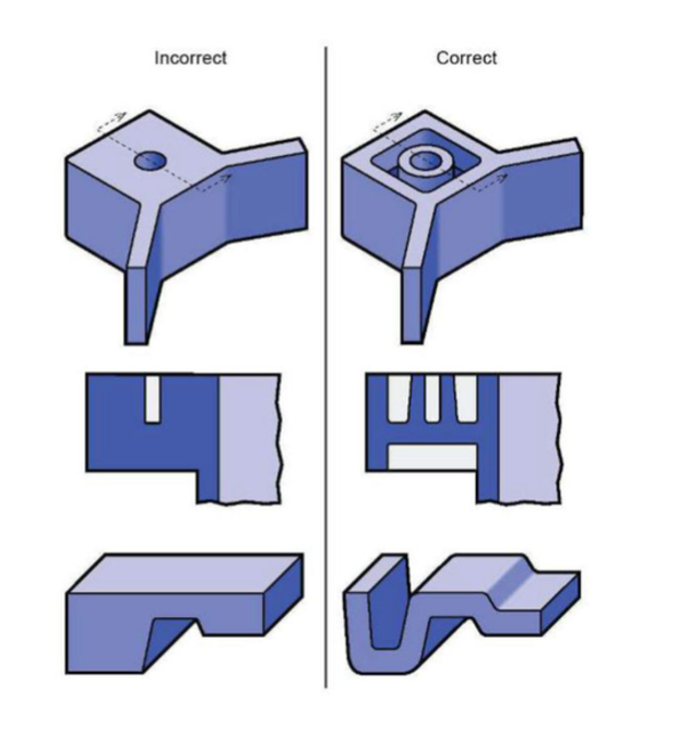
Coring & Uniform Wall Thickness //
Coreorredesign thickareas
to create a more uniform wall thickness
to prevent sink or voids.
Core out thick sections as shown.
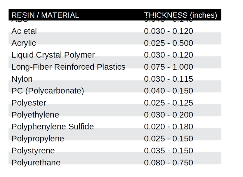
Wall Thickness By Resin Material Guidelines
The proper material selection and observing uniform wall thickness in injection-molded parts, helps avoid potential issues such as sink marks and warpage. We recommended using the guidelines in the table as thicknesses vary by material.
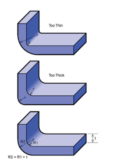
Corner Design //
Makingthe outsideradius one wall thickness
larger than the inside radius will maintain
constant wall thickness through corners.
R2 = R1 + t
Internal and extern corner radii should originate
from the same point.
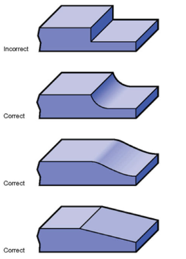
Thickness Transitions //
Rounding or taperingthickness transitions
will minimize read-through and possible
blush or gloss differences. Additionally,
blending reduces molded-in stresses and
stress concentration associated with abrupt
changes in thickness.
Blend transitions to minimize read-through.
Ribs //
Ribs provide a means to augment strength
and stiffness in molded parts without
increasing overall wall thickness.
Other uses for ribs are as follows:
- Act as stops or guides for mechanisms.
- Ribs locate and captivate components
of an assembly.
- They provide alignment in mating parts.
Proper rib design involves five main issues:
thickness, height, location, quantity, and moldability.
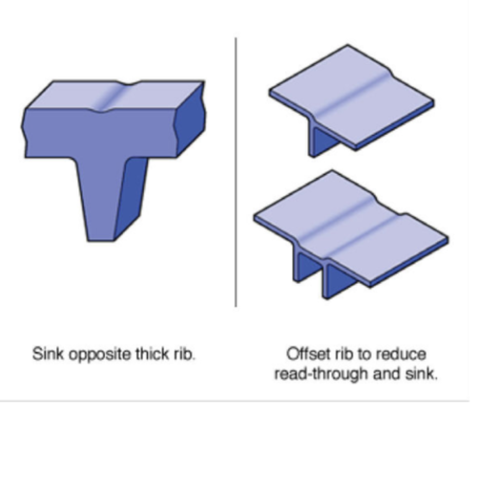
Rib Thickness
There are many factors that determine the appropriate rib thickness. Thick ribs often cause sink and cosmetic problems on the opposite surface of the wall to which they are attached. The material, rib thickness, surface texture, color, proximity to a gate, and a variety of processing conditions determine the severity of sink.
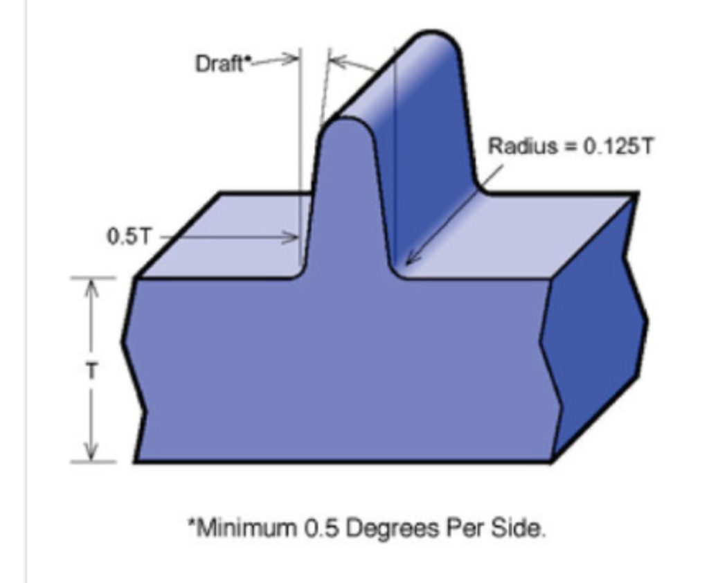
The illustration gives common guidelines
for rib thickness for a variety of materials. These guidelines are based upon subjective observations under common conditions and pertain to the thickness at the base of the rib. Highly glossy, critical surfaces may require thinner ribs.
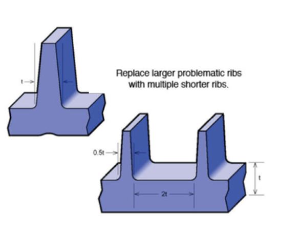
Rib Location & Quantity
The location and quantity of ribs is vital in avoiding exacerbating problems the ribs were intended to correct— e.g., ribs added to increase part strength and prevent breakage may reduce the ability of the part to absorb impacts without failure. Furthermore, a grid of ribs added to ensure part fatness may lead to mold-cooling difficulties and warpage. Typically much easier to add than remove, ribs should be applied sparingly in the original design and added as needed to fine tune performance.
Bosses //
Bosses find use in many part
designs as points for attachment and assembly. The most common variety consists of cylindrical projections with holes designed to receive screws, threaded inserts, or other types of fastening hardware. Generally, the outside diameter of bosses should remain within 2.0 to 2.4 times the outside diameter of the screw or insert.
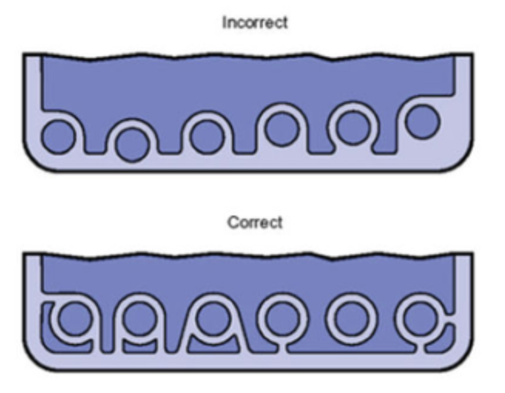
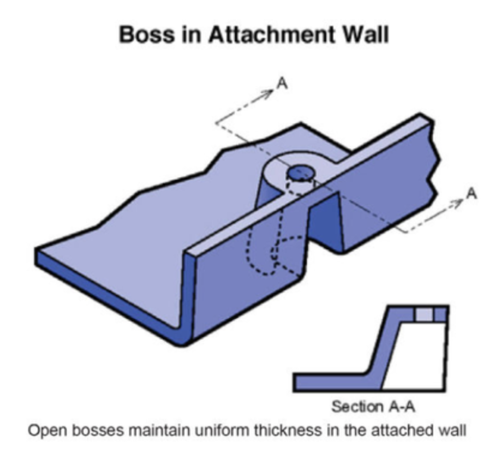
It is suggested avoiding bosses that merge into sidewalls because they can form thick sections that lead to sink. Proper bosses should be positioned away from the sidewall, and if needed, use connecting ribs for support. Try using open boss designs for bosses near a standing wall.
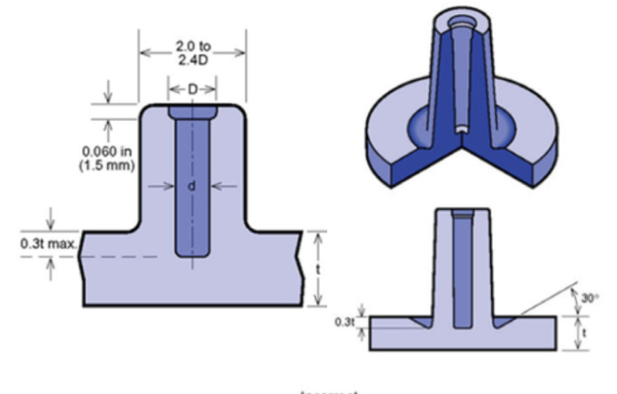
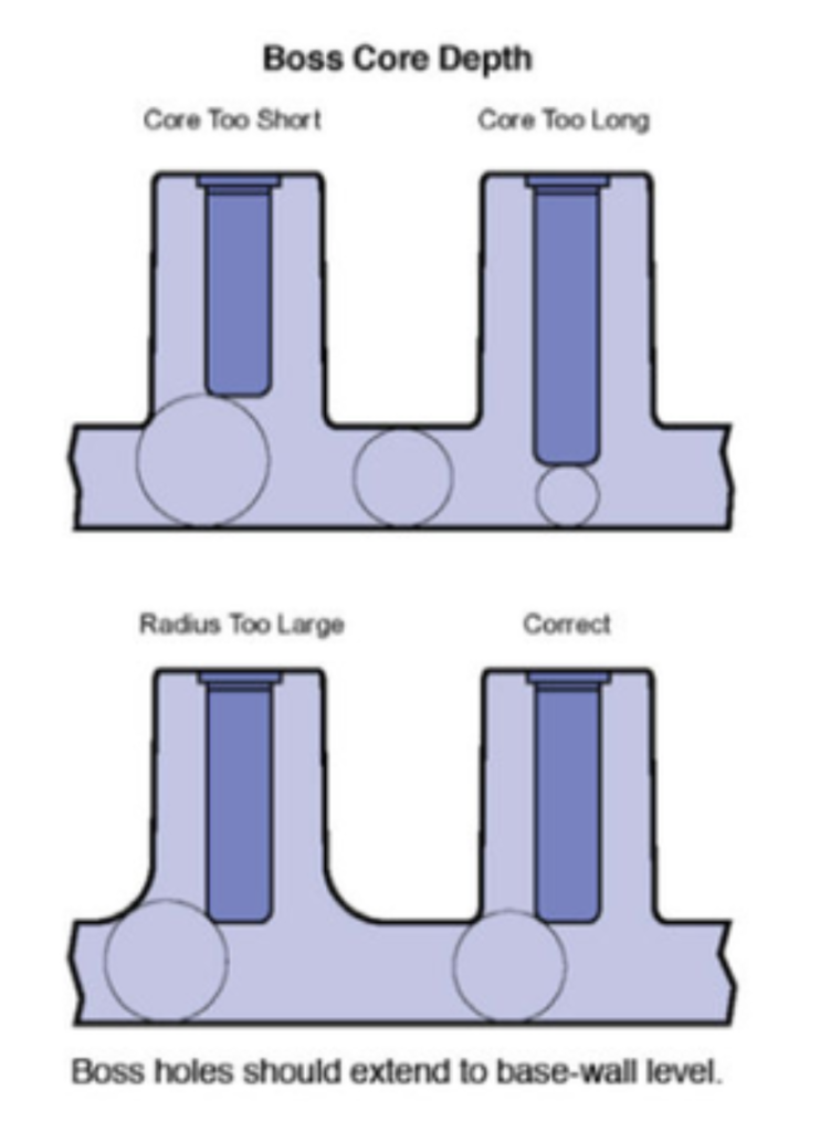
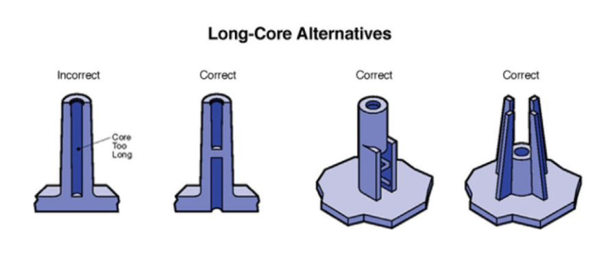
Normally, the boss hole should extend to the base-wall level, even if the full depth is not needed for assembly. Shallower holes can leave thick sections, resulting in sink. Deeper holes reduce the base wall thickness, leading to filling problems, knitlines, or surface blemishes. Because of the required draft, tall bosses (those greater than five times their outside diameter) can create a filling problem at their top or a thick section at their base. Additionally, the cores in tall bosses can be difficult to cool and support. Think about coring a tall boss from two sides or extending tall gussets to the standoff height instead of than the whole boss.
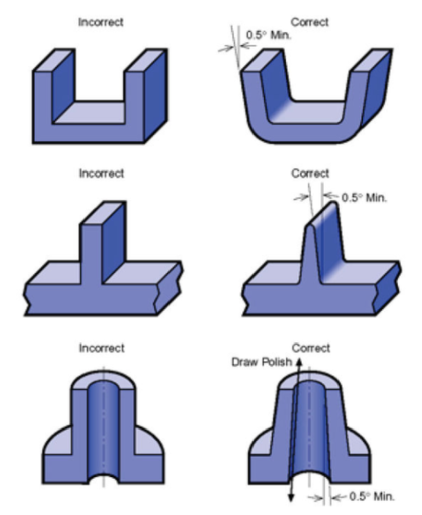
Draft Angles //
Providing angles ortapers onproduct features such as walls, ribs, posts, and bosses that lie parallel to the direction of release from the mold eases part ejection.
How a specific feature is formed in a mold determines the type of draft needed. Features formed by blind holes or pockets (such as most bosses, ribs, and posts) should taper thinner as they extend into the mold. Surfaces formed by slides may not need draft if the steel separates from the surface before ejection.
Other guidelines for designing draft include:
- Draft all surfaces parallel to the direction of mold separation.
- Angle walls and other attributes that are formed in both mold halves to assist ejection and retain uniform wall thickness.
- As a general rule, use the standard one degree of draft plus one additional degree of draft for every 0.001 inch of texture depth.
- Use a draft angle of at least one half
degree for most materials. Design permitting, use one degree of draft for easy part ejection. SAN resins typically require one to two degrees of draft.
Is Your 3D File Tooling-Ready?
Check your design against our quick injection molding guidelines. Ensuring proper draft angles and uniform walls now will save you weeks of back-and-forth communication later.