I’ve opened maybe 800 STEP files in the last three years. Maybe a hundred of them made me wince.
Not because the part was badly designed. Because the file was sent in a way that guaranteed three extra rounds of emails, two design changes, and a two-week delay that the buyer then blamed on the supplier.
This article is for the mechanical engineers and product designers sending CAD files to an injection mold manufacturer for quoting. Do these six things before you hit send, and you will save yourself more time than any negotiation tactic ever could.
1. Draft angles are not optional. They are the difference between a part that ejects and a part that welds itself to the core.
Every injection molded part needs draft. Not some parts. Not most parts. Every. Single. Surface. That runs parallel to the mold opening direction.
Here is the rule: minimum 0.5 degrees for a textured surface, 1 degree for a smooth surface, and 2-3 degrees if the surface has any depth to it beyond about 20mm. A textured surface needs more draft because the texture creates mechanical interlock — the plastic flows into the micro-grooves of the texture and grips them like sandpaper.
The worst CAD file I ever received had zero draft on a 45mm-deep ribbed housing. Zero. The designer had modeled it perfectly vertical because that is how it looked in the render. The mold took an extra week because the cavity had to be split into four side actions to even make ejection possible. That week cost more than the designer’s time to add draft in CAD.
Quick check: if your CAD software has a draft analysis tool (SolidWorks, CATIA, and NX all do), run it before exporting. Any surface that shows up red or blue depending on the pull direction — that is a surface that needs draft.
2. Wall thickness should be uniform. Not mostly uniform. Uniform.
This is the most common CAD mistake. And I understand why it happens. In mechanical design, thicker walls mean stronger parts. You add a rib for stiffness. You thicken a boss because a screw goes in there. Every decision makes mechanical sense.
But plastic does not cool like metal. A thick section stays hot while a thin section solidifies. The differential shrinkage pulls material inward and creates sink marks — dimples on the surface that look like the part is collapsing on itself. The sink mark is exactly where the thick section meets a thin wall, every time.
The guideline: keep wall thickness between 1.5mm and 3mm for most engineering plastics. If you must thicken a section — a boss, a rib base — keep the thickness ratio below 60% of the nominal wall. A 3mm wall with a 2mm rib is fine. A 2mm wall with a 3mm rib base will sink. Every time.
Also, transitions matter. A sudden step from 2mm to 4mm is worse than a gradual taper. If you need a thick boss, core it out from the back side. A cored-out boss keeps wall thickness uniform while maintaining the diameter the screw needs. Same strength, zero sink.
3. Sharp internal corners are stress risers. They are also mold killers.
A 90-degree internal corner does two bad things. In the part, it concentrates stress and becomes a crack initiation point. In the mold, it forces the cutter to stop at a sharp tip, which means the remaining steel has to be burned out by EDM. EDM is slower and more expensive than CNC milling.
The fix is a radius. Minimum 0.5mm on internal corners, preferably 1mm or more. But here is the trick nobody teaches: the radius should be consistent. A part with 0.5mm radii on some corners and 2mm radii on others means the CNC programmer has to do multiple tool changes. Multiple tool changes means longer machining time. Longer machining time means a more expensive mold.
Pick one internal radius for the entire part, or at most two. Tell your supplier what they are. They will nod approvingly.
4. Undercuts are fine. Undercuts the designer did not notice are not fine.
An undercut is any feature that prevents the part from ejecting straight out of the mold — a side hole, a clip, a recess, a thread. These are not deal-breakers. They just require slides, lifters, or collapsible cores, and each of those adds cost.
What is a deal-breaker is an undercut that the designer did not realize was an undercut. A rib that curves inward. A snap hook that faces the wrong direction. A boss that is placed 2mm from a sidewall, creating a tunnel that no cutter can reach.
Before you export the STEP file, sit down and imagine the part pulling straight out of a block of steel along a single axis — the mold opening direction. Anything that catches, snags, or traps is an undercut. Mark it. Decide if it is intentional. If it is not, fix it in CAD. If it is, tell your supplier so they can quote the slides.
5. Gate location is the designer’s decision, not the mold maker’s guess.
The gate is where molten plastic enters the cavity. It leaves a small mark — a vestige — on the finished part. If the designer does not specify where they want the gate, the mold maker will put it in the most convenient location for mold construction. That location might be on a visible cosmetic surface, or right through a logo, or in a spot that creates a weld line right where the part flexes.
You do not have to be an expert in
You do not have to be an expert in injection mold design to make this decision. You just have to know which surface of your part is A-side (visible, cosmetic) and which is B-side (hidden, functional). Tell the mold maker: ‘Gate on B-side only. No gate marks on A-side.’ That is enough. They will figure out the rest.
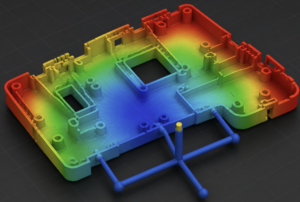
Even better: if you have a mold flow simulation, run it once and note the recommended gate location. Include that screenshot with your STEP file. A mold maker who receives a CAD file with a gate preference and a flow analysis screenshot knows they are dealing with someone who understands manufacturing. Their quote will reflect that confidence.
6. Send the right file format. STEP, not STL, not native CAD.
This is the simplest rule and the most frequently broken.
STEP (.stp or .step) is the universal standard. It carries solid geometry with actual curved surfaces — not a mesh approximation. An STL file is a triangle mesh. It looks like a part but is actually a collection of flat facets approximating curves. A mold maker cannot use an STL for CAM programming. They will ask you to resend the file, and that costs a day.
Native CAD files (SolidWorks .sldprt, CATIA .CATPart) are fine if your supplier uses the same software. Most Chinese mold shops use SolidWorks, NX, or Cimatron. If you are not sure, STEP AP214 is the safe bet. It carries colors and layer information that AP203 does not.
And please, one file per part. Not an assembly with 47 components where 45 of them are hidden. Export the cavity geometry you want quoted, and nothing else.
The five-minute checklist before you export
Here it is. Tape this to your monitor.
| Check | Answer |
| Draft on every surface? | Yes / No. If No, fix it now. |
| Wall thickness uniform? | Checked with thickness analysis. Sink risk noted. |
| Internal corners radiused? | All > 0.5mm. Consistent radii across part. |
| Undercuts identified? | Marked. Intentional ones noted for supplier. |
| Gate surface preference? | A-side or B-side specified. |
| File format correct? | STEP AP214. Single file. No assembly clutter. |
That took you five minutes. It will save your supplier two hours of back-and-forth questions. It will save you a week of schedule delay. And it will make your mold quote more accurate because the supplier is reading a manufacturable part, not guessing at one.
Good CAD files do not cost more to produce. They cost less to quote, less to build, and less to fix. The difference between a bad file and a good file is not skill. It is five minutes of checking before you hit export.
Got a CAD file you want someone to look at before quoting? Reach out through
Got a part design you want reviewed before you send it out to quote? Reach out through our engineering team. We do free DFM reviews with no obligation. Mostly because it saves everyone time — and honestly, we would rather give you feedback now than fix the mold later.
————————————————————————————————————————
Author: Jack Qiao runs engineering projects at Kysen Mold, a Shanghai-based injection mold manufacturer with a 1,120 sqm facility and ISO 9001 certification. He opens approximately five STEP files a day and has strong opinions about draft angles.
Website: www.kysenmold.com